


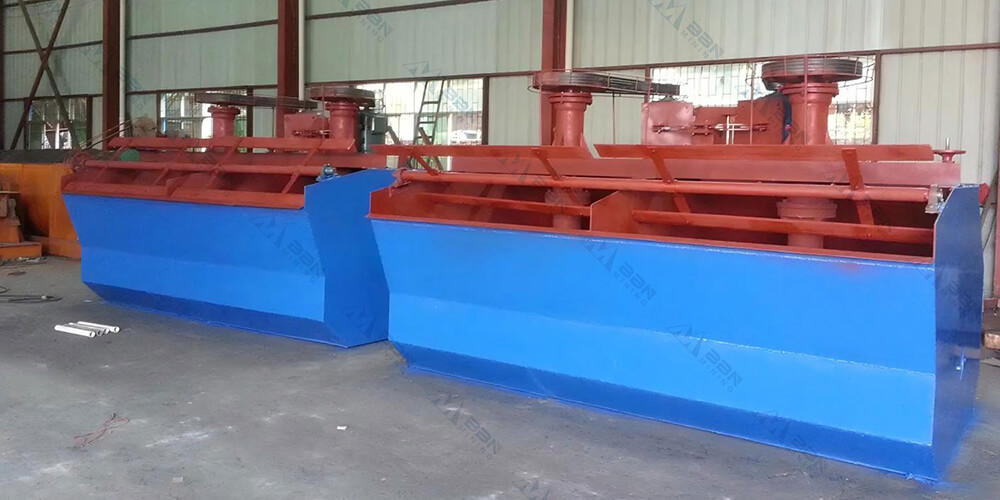
The XJ-type flotation machine (also known as the XJK or A-type) was introduced from the Soviet Union in the 1950s and is one of the earliest mechanically agitated flotation machines used in my country. Although it has been replaced by some newer flotation machines in recent years, it is still widely used in small and medium-sized mineral processing plants due to its mature structure, simple operation, and strong adaptability. The equipment consists of two flotation cells forming a unit. The first cell is a suction cell (with a slurry inlet pipe), and the second cell is a direct-flow cell, with a connecting chamber in between to facilitate gravity flow and circulation of the slurry.
Working Principle
The XJ-type flotation machine achieves pulp agitation, aeration, and frothing mineralization through impeller rotation:
1. Air Intake and Agitation: The motor drives the impeller to rotate at high speed, generating negative pressure within the impeller chamber, automatically drawing in air through the air inlet pipe.
2. Mixing and Refining: The pulp and air are thoroughly mixed in the impeller zone, intensely agitated and broken down into numerous tiny bubbles.
3. Mineralization and Flotation: Hydrophobic mineral particles selectively adhere to the bubble surface, forming mineralized froth that rises to the liquid surface.
4. Scraping and Separation: The froth layer is continuously scraped off by a scraper, becoming the concentrate product, while the tailings flow into the next processing stage.
The entire process requires no external air supply, possessing self-aspirating air and pulp capabilities, and can independently form a flotation circuit.
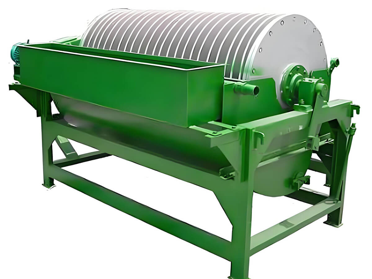
Product Structure
The XJ-type flotation machine mainly consists of the following components:
- Impeller and main shaft: The conical, backward-inclined blade design, similar to a high-specific-speed centrifugal pump, provides strong slurry conveying capacity.
- Cover plate and guide vanes: The cover plate is equipped with 18-20 inclined guide vanes (55°-60° inclination) to guide the slurry flow.
- Air cylinder (vertical pipe): Used to install the slurry inlet pipe, middlings return pipe, or slurry circulation pipe; the orifice diameter can be adjusted via a pull rod.
- Circulation orifice and gate: Located at the bottom of the air cylinder, it controls the slurry circulation volume, ensuring stable slurry supply to the impeller center.
- Integrated aeration and stirring assembly: The impeller, cover plate, main shaft, air inlet pipe, etc., are assembled into one unit, facilitating maintenance and ensuring assembly concentricity.
The slurry level in each flotation cell is adjusted via a gate, making the control system flexible and reliable.
Product Advantages
1. Strong Self-Aspiration Capacity
Simultaneously aspirates air and slurry, eliminating the need for additional blowers or sand pumps, simplifying the process and reducing energy consumption.
2. Compact Structure and Easy Maintenance
The integrated aeration and stirring components facilitate disassembly and replacement; the horizontal configuration allows for process changes and equipment layout adjustments.
3. Optimal Slurry Circulation
The circulation hole design adjusts the internal slurry flow rate, reducing coarse sand sedimentation and improving flotation stability.
4. Adaptable to Multiple Process Requirements
Supports roughing, cleaning, scavenging, and reverse flotation operations, suitable for mineral separation at different stages.
5. Stable Operation and Low Energy Consumption
Moderate stirring intensity ensures good solid particle suspension, a stable liquid surface, and relatively low power consumption.